Medium Voltage Capacitors, M.V.Capacitors, Mumbai, India


   EPCOS
Phase Cap Capacitor
Phicap Capacitor
Square Cap Capacitor
AC (MFD Capacitors)
Power Factor Controller
Capacitor Duty Contactors
Thyistor Switch Module
Three Phase Filter Reactor
Power Analyser
LV APFC Panels
Medium Voltage Capacitors
MV Capacitor Switch
MV Vacuum Contactors
Pole Mounted RPC System
Pad Mounted RPC System
Station Type RPC System
 
   JAIVIC Power Capacitors
M.P.P. Dry Type
M.P.P. (Oil) Type
A.P.P. Type
 
   TIBCON AC Capacitors
   
A.
AC Run Capacitor
PP.Can Pin/Wire Type
Al. Can Pin / Wire Type
   
B.
Power Capacitor
  M.P.P. Dry Tyre
 
   VISHAY
M.P.P. Gas Filled Power Capacitor
   
Shreem Power Capacitor
Agristar (MPP)
Cylindrical Industrial (MPP)
Cylindrical Gas Filled
Industrial Rectangular (MPP)
Heavy DUty Double Dielectric (MPP)
APP ( Heavy Duty)
Power Factor Controller
Series Reactor for harmonic Protection
   
ISABELLENHUTTE
ISABELLENUTTE HEUSLER GMBH & CO. kG
Surface Mount Assembly
Hybrid Assembly
Heatsink Assembly
Bus Bar Assembly


Medium Voltage Capacitors


Medium Voltage Capacitors  Medium Voltage Capacitors
   
 
Medium Voltage Capacitors


Medium Voltage Power Factor correction directly related to the technical management of transmission and distribution network. The major benefits are :

 
Power quality . Increased voltage profile in substations and at receving ends.
 
Improving the operating cost of an installation. Decreasing reactive power demand and therefor reduction of apparent power with two highly important aspects.
  Reducing losses
  Increasing the performance of transformers and installation.
   
  Power quality, voltage level
 

There are two possible situations : controlling voltage in substations and at reveiving end of medium voltage distribution lines.

Controlling Voltage at substations.


One of the most critical point in the distribution of electrical energy is maintaining voltage at receiving end. The most usual crition is maintaining medium voltage above its nominal value.

To achieve this Medium voltage Capacitor banks are used. In fact a voltage rise may appear by connecting capacitor banks at the point of connection.

* Controlling voltage at the reveiving

Capacitor case
The CRFA stainless Steel container is treated with a primer and finish coat of paint suit the application end of distribution lines.

Voltagea at receiving ends nomally decrease because of every long length of conductors / cables. This is of imprtance in area of rural distribution or where consumers are widely dispressed.

If capacitor banks are installed at the end of line that shall decease voltage drop losses in conductors / cables.

Improving the operating cost of an installation

Generation, transmission and distribution of energy are responsible for a significant degree of energy losses.

These losses may be divded into :
* Losses in generation station and MV/HV substances.
* Losses in transmission system
* Losses in HV/MV substation.
* Losses in distributopn line.

The best way of reducing losses in an MV distribution lines is the installation

I2R Losses in line P (KW) = 3 R. I2.L
Reactive consumption in line Q (KVAr) = 3. x I2.L
Reduction in losses after installation of capacitor Δ P = R [p2 +(Q-Qc)2] / V2. L

P = Active power, Q = Reactive without capacitor, QC = Capacitor bank in MVAr, I = Current,
V = System voltage in KV, R = Resistance in Ohms/Km, X = Reactance in Ohms / Km, L = Length of line in Km.

   
  Manufacturing Characteristic of M.V. Capacitors


Basic Construction

High voltage capacitors employ a technique wherein the dielectric comprises several layers of polyprolylene film
impregnated with an insulating fluid. Electrodes are made from thin aluminium foils. A high voltage capacitor is made of a number of elements connected in a series - parallel arrangement. The total number of elements isdetermined operating voltage. Depending on capacitors rating each elements can be fuse protected.


After impregnation the complete assembly is hermetically sealed inside a steel container.

The Dielectric
The all-film dielectric used in high voltage capacitors is manufactured from the most advanced polypropylene film available which has the following benefits :

Reduced dielectric losses

Decreased variation of capacitance with ambient temerature, to obtain a more constant output

Impregnating Medium
The impregnation fluid, has has been specially formulated for power capacitors. It has been selected for both its physical and electrical properities and its high resistance to extremes of temperature. The fluid is non chlorine bio-degradable and contains no PCBs.


Internal Element Fuses

Modern power capacitors are designed to withstand high stresses where the electric gradient in the dielectric is typically in excess of 50-60 volts per micron. Depending on the voltage rating the capacitors in EPCOS range incorporate highly efficient back-up protection so that each individual element is safeguarded by a built-in, series connected fuse. In The event of a localised breakdown of the electric, only the faulty element is disconnected by the fuse and any subsequent reduction in capacitor output is minimized.

Capacitor Case

The CRCA container is treated with a primer and finish coat of paint to suit the application.

Capacitor Bushing
Depending on requirements, one teo or three porcelain bushings are fitted to the container. These have impulse withstand rating of 75KV, 95 KV, or 150 kV according to application.

Standards
IS- 13925 / 1988 ( supersending the old
IS : 2834-1986), IEC 871-1, IEC 871-1, IEC 871-2.
Shut capacitors for AC power system having rated voltage above


Capacitor Units  
Type healing Dieelectric Welded CRCA Stainless Steel tank, Liquid design, non-self Polypropylene film,
Impregrant Non PCB film
Connections 1-phase / 3- phase units (depending on voltage rating)
Tolerance on capacitance -5 % + 10 %
Discharge mechanism Discharge resistance provided
Discharge time < 50 V within 10 min
Capacitor unit protection Internal / External fuses depending on rating
Total looses including discharge resistors < 0.2 watts / KVAr
Rated Voltage (Vn) As per requirement of capacitor bank voltage
Rated frequency 50 / 60 hz
Inslution level As per requirement of capacitor bank voltage
Continuos over voltage 1.1 x Vn (rated voltage) for 12 hrs daily
Continuos over current 1.3 x In (rated current)
Temperature range -25 0C to + 50 0 C
Capacitor Tank  
Type Inddor / Outdoor
Connections 1 - phase / 3-ph Detta / Si
Terminal arrangement Outdoor on post inslulators
Indoor Cable entry hole / Box as per customer requirement
Bus bar material Aluminium Copper as per customer requirement
   
  Recommended Capacitor Bank Protection


This shouldbe designed to protect the capacitor bank against overloads current. With the modern low loss capacitor, the risk of thermal breakdown, the risk of thermal breakdown is minimal and any failure more usually results from dilectric breakdown. This occurs as a result of over voltage which, in many cases, is caused by excessive harmonic current. Protection can be achieved by means of peak value voltage sensitive relays or current relays having characteristics designed to prevent over voltage.

Where capacitors are connected to a network fitted with fast reclosing breakers, they must be fitted with undervoltage protection to ensure disconnection at voltage drop-out. They must not be reconnected until the residual voltage has fallen below 10 % of the rated value.

External Fuse protection

External fuse can be used to provide protection for individual capacitor units and the smaller capacitor bank. The selected fuse rating must take account of overvoltages overcurrents and switching transients such that spurious operation is avoided.

Unbalance Protection

The purpose of unbalance a faulty bank before overvoltages greater than 10% appear on remaining healthy units. To achieve this, the capacitor units are arranges in single star or double star connections. In case of single star protective relay can be operated by sensing voltage unbalance across by RVT whereas in case of double star protective relay can be operated by sensing fault current of CT connected between neutral of two stars.

Damping Reactors
When switching a capacitor bank, high current transients appear. These can be particularly high if the bank is connected in parrel with another bank which is already energised.

It may, therefore, be necessary to limit this inrush current by connecting a reactor in series with the capacitor bank.
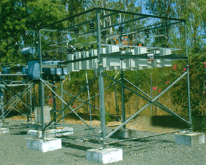
Enclosures
A complete range of enclosures can be offered to suit all the applications, selected from:

* Ingress Protection ratings up to IP55 for indoor or outdoor use.
* Cubicles, tanks o open racks, floor mounted.

Asociated Equipments

All the following equipments can be offered :
* Controlling switchgear for manual or automatic control.
* Voltage and current transformers.
* Current limiting reactors, Detuning and filter reactors-iron and air-cored.
* Out-of-balance protection systems and Lightning Arrestors.

Information required with enauiry
* Requirements is new or for replacement
* Dimensions of existing units in case of replacement
* Highest system voltage and frequency.
* Temperature category.
* Rated output required in KVAr.
* Single phase / Three Phase.
* Connectiom : Star / Double Star / Delta
* Basic Insulation level
* Location : Indoor / Outdoor
* Fuses : Internal / External Fuse.
* Type of load.
* Single line diagram of the electrical system
* harmonic details if available
* Protection required
* Associated equipmets required.


Home - About Us - Products - Contact Us - Feedback - Site Map Designed & Hosted by : MID  Promoted by : GID