OUR RANGE OF PRODUCTS :
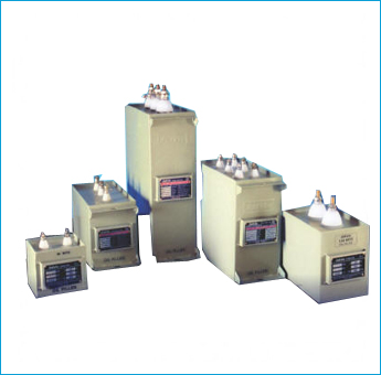
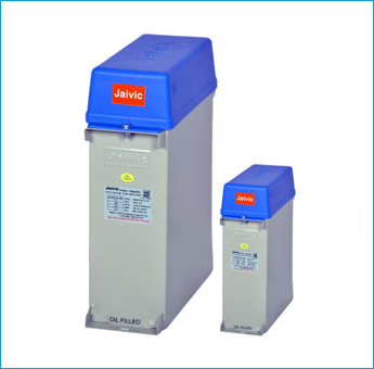
• LT-APP CAPACITOR UNIT : 1 TO 30 KVAR
• LT-APP CAPACITOR BANKING : 50K-100 KVAR
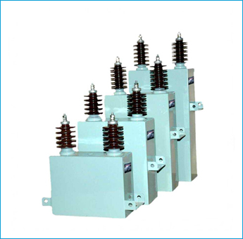
• HT-APP CAPACITOR UNIT : UPTO 600 KVAR 11 KV
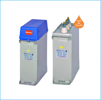
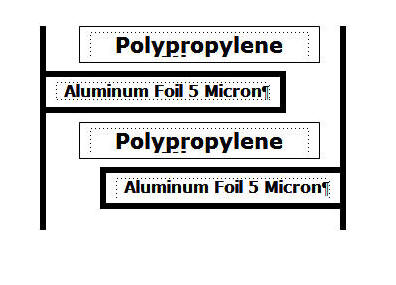
Jaivic ALL PP Capacitors are manufactured using Double hazy and double thick polypropylene films between two electrodes of soft annealed thick Aluminum Foil. The Dielectric of PP-type capacitor takes the form of a low loss polypropylene Film+Foil elements completely dried in high vacuum & impregnated in NPCB oil and hermetically sealed.
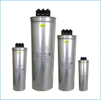
Flat wound elements on Good Quality winding machine result in Zero defect windings with accurate outputs. Most compact, Accurate, Zero defect International grade windings are made available for further processing. End Impregnation of the capacitor is done with the help of pretreated Non-Toxic friendly impregnated in a Vacuum Impregnation chamber at a very high level of Vacuum. Final Capacitors are tested as per IS 13585 specifications (as amended up to date) with the help of very accurate testing equipments. Our manufacturing range includes LT-APP, HT-APP, MPP OIL, MPP DRY, MPP Aluminum Cylindrical and other MFD condensers. We also undertake manufacture of capacitors of single phase and special voltage application.
APP capacitors are Impregnated with the help of non-toxic friendly liquid at a very high vacuum resulting In following advantages
❒ The Vacuum Drying and impregnation procedure frees the dielectric from any voids end minimize the occurrence of partial discharges. This results in long life expectancy and extremely stable electrical characteristics.
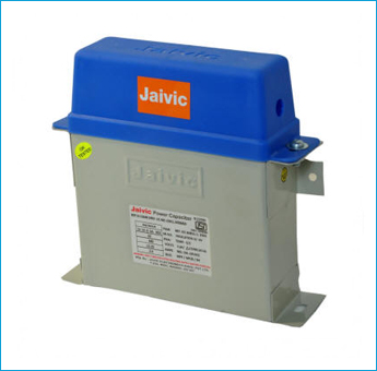
❒ Jaivic impregnated APP Capacitors are hermetically sealed, hence do not have any atmospheric effect. Capacitor stacks are encased in metal containers of adequate thickness. The containers are hermetically sealed, to avoid rusting, metal containers are electroplated which also result in rust free attractive and durable painting.
❒ Level of liquid impregnant is maintained sufficiently above active stacks; in liquid impregnant transfer of heat by conduction and convection mode is fast. This result in uniform cooling of capacitors. In turn reducing temperature rise of active elements. This gives an extra edge by increasing life of the capacitors and to take care of rugged service conditions.
❒ With free flow of impregnant inside capacitor containers, cooling of capacitor is uniform, making it very suitable for tropical and super tropical conditions.
❒ The Zinc contact layers forms a stable contact with the foil & guarantee a very high resistance to Impulse charges reducing the Self-Inductance of the Capacitor.
❒ Extended foil design.
❒ Specially Design for super tropical Countries Like India.
❒ Suitable for heavy duty application.
❒ Most reliable for harmonic infested systems.
❒ Very low losses through the application of hazy polypropylene dielectric and aluminum foil.
❒ Low energy consumption.
❒ Highest Inrush Current Withstanding Capacity.
❒ Better Thermal Conductivity & Higher Viscosity of Impregnating oil.
❒ Production Process adopted is identical to the Process of HT Capacitor.
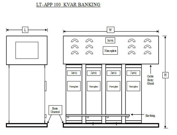
More than 50 kvar units are provided with Banks of our Standard Rating.
Energy conservation is the most important for all because the cost of energy for industrial production is reflected in the cost of goods produced, it is in the interest of all, particularly those engaged in any capacity in production to save as much as possible.
There are many ways in which this can be brought about. One of the most effective ways from the industrial point of view is the installation of Power Capacitors. By installing Power Capacitors the Power Factor-can be improved, the improvement in Power Factor will decrease the maximum demand of the system.
What is Power Factor?
Any industrial installation is fed from a high voltage system and comprises of:-
1) A Transformer Station.
2) “Resistive” loads-such as ovens, radiators, filaments, lamps, etc.
3) “Inductive” loads-such as transformers, motors, etc.
It should be noted that the actual power consumed is lower than the Apparent Power and this ratio is called the Power Factor.
I.e. Useful Power = Power Factor < 1
Apparent Power
The advantage of a better Power Factor are multifold and all results in substantial economy in the
Operation of electrical installation.
1) Cutting down penalties for excessive consumption of reactive energy.
2) Reducing line losses.
3) Increasing line power carrying capacity.
4) Increasing power available at supply transformer.
5) Reducing Voltage drop.
Capacitors can be used as individual units or in Banks.
Individual units of 1 to 30 kVAr ratings can be used for small units. For the bulk power consumers whose installed capacity is more than
100 KW may go for Banks of capacitors with or without automatic P. F. control relay. If the load fluctuation is more, as in Cement plants,
Rolling Mills etc., they need Automatic Power Factor control relay to suit the load condition.
The saving effected by installing P.F. correction capacitors can be indicated by following example:
Consider:
Maximum Load 125 KW
Present P. F. 0.75
Required P. F. 0.99
Maximum demand at 0.75 P. F. = 125 = 166.6
kVA
0.75
Maximum demand at 0.99 P. F. = 125 = 126.26 kVA 0.99
Reduction in Max. Demand = 40.34 kVA
Saving in monthly charges @ Rs. 300/- per kVA (MSEB rates) : Rs. 12,102/-
Size of Capacitors required for this unit.
(Multiplying factor from the table)
For improvement of P.F. - From 0.75 to 0.99 i.e. 0.740
Therefore capacitor size = 125 x 0.740
= 92.5 kVAr , say 95 kVAr.
Total Cost @ Rs. 170/- per kVAr (MPP Capacitors) Rs. 16,150/-
The entire cost is recovered in: Rs. 16,150 = 1.33 Months. = 40 Days
Rs. 12,102
If the penalty for low P.F. & rebate for Power Factor is taken into account this recovery is achieved in still less period of time.
If rebate for better P.F. is considered into calculation, this recovery will be in less than one Month period.